FDR Display - User Manual
Display to be used in companion with FDR device connecting to FDR via WIFI. Allows the user to visualize FDR data and current status.
This device is not an approved or certified aviation instrument.
It must not be used as a primary source of navigation, attitude, airspeed, altitude, flight control, or aircraft performance information.
Use of this device does not replace any certified aircraft system or instrument.

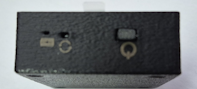
The Display has three external buttons:
- On the side there is the
Power Button - On the top side we have buttons to control the zoom scale on the radar page
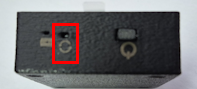
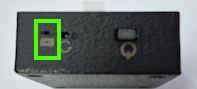
Also on the side where the Power Button is located, there is a small hole to allow to perform a Display Reset, and there is also a LED Light related to battery charging.
Display Dimensions
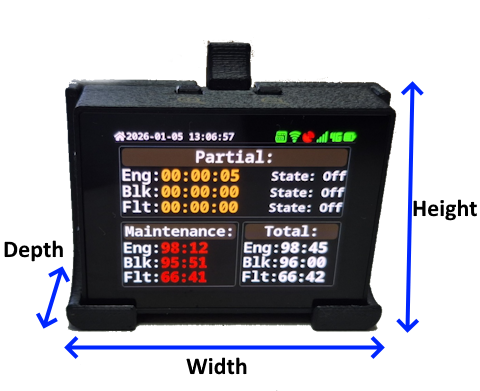
Display is relatively small and light, dimensions are:
- Width: 64mm
- Height: 48mm
- Depth: 18mm
When coupled with the mounting base the dimensions are:
- Width: 70mm
- Height: 51mm (60mm)
- Depth: 27mm
The mounting base has two 4mm holes for support, spaced at 30mm.
Installation
The Display can be installed using the mounting base supplied, the base has two 4mm holes for support, spaced at 30mm. It should be installed in a location with good visibility for the pilot, avoiding direct sunlight on the screen.
The Display should not be installed in a location that may obstruct the pilot view or interfere with aircraft controls or instruments.
If no permanent installation is required the Display can be used without the mounting base, just placing it on a flat surface or using for example a Velcro type fastener to hold it in place.
Powering the Display
The Display supports battery operation, by default the device does not contain internal battery since its considered to be a "semi-permanent" installation. The device is expected to be powered directly via FDR with extension cable supplied.
We can arrange cables with different lengths than the default 1m length, please contact us.
Check FDR Power Connections Options.
If battery operation is required, contact us to order the Display with battery included.
When operating on Battery In order to turn ON the Display press the Power Button for around 2~3s until the screen turns on. To turn OFF the Display press the Power Button for 3s until the Display will turn the screen OFF at that point release the Power Button, while pressing the Power Button an extra symbol will appear on the Display indicating that is detecting the Power Button being pressed.
When using the USB (Type-C) connector, the Display will automatically turn ON and the Power Button will have no effect, after removing the USB cable (if the Display has an internal battery) it is necessary to turn OFF the Display using the Power Button.
The expected battery life is around 8h of use for a full charge battery (depends on color theme in use).
The Display Brightness has some impact on battery life (more noticeable when using the Light color theme), although reduced, between 100% and 40% brightness the power consumption reduces about 10%, a change from 100% to 80% a reduction of maybe 5%.
In case the Power Button stops responding or the Display firmware is stuck it is possible to force a Reset. On the enclosure side there is a small hole to use to reset the Display, use for example a paper clip to press the button via the hole.
When performing a Reset with the display being powered via battery, the Display will turn off.
In case the Display has an internal battery, and it's being powered via USB, when removing the USB cable (or cut the power to the USB Charger) the Display will continue ON using the internal battery, in that case it is necessary to turn OFF the Display using the Power Button.
Battery Charging
Only for models with internal battery
Use a standard phone charger with USB output, the Display has a USB-C receptacle and requires a maximum of 5W while charging.
A complete charging cycle should take around 2h~3h.
On the Display enclosure lateral there is a small LED Light (GREEN) that indicates the charging status:
ONBattery is chargingOFFBattery charging is complete
The current hardware is not capable of detecting in the battery is currently charging and if the charging cycle has completed. The System page may indicate 100% charge and when removing the USB cable the value may drop to 90% (example), when fully charged it should drop to 98%~99% the value is a little battery dependent.
Power requirements
When powered via USB, the power requirements are:
- While charging, between 3W and 5W (In case Display has internal battery)
- In Standby (Not charging, display active) < 1W
When powering the Display via USB connector, the user can use a standard USB Charger or be power the Display directly from FDR device with the supplied cable.
Connection to FDR
The Display connects to FDR device via WIFI, in order to connect the Display to FDR access the Settings / Setup Wifi menu. (Make sure that FDR is powered ON).
There should appear a WIFI network with the name FDRxxxxxx where xxxxxx is the FDR device serial number. In case no network appears press the Refresh button to force a new search for available WIFI networks.
It can appear more than one network with FDR in the list, in that case select the correct one based on the serial number or eventually based on the RSSI signal strength most likely it will be the strongest network.
After selecting the correct network press the Connect button, after a few seconds the status should change to Connected and the WIFI icon on the top right corner should change to green color.
Display Color Theme
The user can choose between two color themes, Dark and Light, on very "bright" environments the Light theme may facilitate the display visualization. To choose the theme color check Menu Option Display.
| Dark Theme | Light Theme |
|---|---|
 |  |
The display is reflective. In very bright conditions, depending on the angle of sunlight, it may become harder to see.
To improve visibility, you can apply an anti-glare screen protector (such as those designed for phones or tablets).
Main Screen
Upon powering the Display a Warning screen will appear, it is necessary for the user to touch the screen to confirm that user has read and understood the warning message.
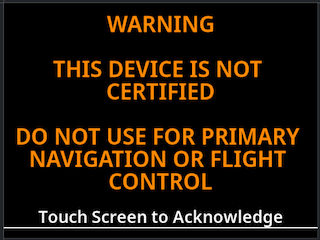
It is possible to acknowledge the warning message by pressing any of the external buttons.
After acknowledging the warning, the Display will show the main screen:
On the TOP Right side the Display shows the current Date/Time (based on GPS Date), on the left side there are a couple of symbols to quickly get the current Display/FDR status:
| Name | Symbol | Description |
|---|---|---|
| Battery Level | Indication of Battery Level, color coded: - Yellow: Charging (symbol with extra indication of charging) - Red: Empty (less than 5%) - Orange: Lower than 20% - Yellow: Lower than 40% - Green: Higher than 40% Symbol has “levels” to indicate battery state | |
| LTE Status | Indication if FDR is currently registered in LTE Network, color coded: Red: Modem OFF Blue: Modem waiting for registration Green: Modem Registered on Network | |
| LTE Network Signal | indication of LTE Network Signal Strength, color coded: Red: No Signal Orange;: Weak Signal Yellow: Medium Signal Strength Green: Good Signal Strength | |
| GPS Status | GPS Status, this is the GPS status of FDR: - Green: GPS is FIX - Red: GPS Not FIX (or no data related to GPS) | |
| Wifi Status | Wifi Status, color coded - Green: Connected to WIFI Network - Orange: Attempting to connect to an WIFI Network - Red: Not connected to a configured WIFI Network - Gray: No WIFI Network Configured | |
| Server Status | Indication of connection status with FlyData server, color coded: Red: Not connected Orange: Attempting to connect Green: Connected | |
| Firmware Update | Only shown in case there is a firmware update available to the display. Requires connection to a WIFI Network with internet access | |
| Power Button | Feedback to user that Power Button is being pressed, only visible while pressing the Power Button | |
| Individual Alerts | Indication that there are “airplanes” configured to ignore collision alert. The number indicates how many “airplanes” have alerts disabled, not visible if no alerts disabled |
Screen Navigation
When in the main screen (or any screen that has the top symbols) there are two shortcuts.
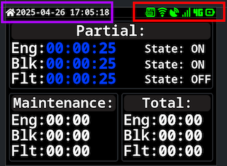
Pressing the icon area (top right - Purple) will change to the Settings Page. Another shortcut to Settings page is a Short Press on the Power Button.
Pressing the time stamp (top left - Red) will change to the Main Page.
To navigate between the Display main screens there are two possibilities:
- Use the enclosure top buttons to switch pages
- Use
Swipegestures (Left / Right) to switch between pages
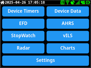
Screen Selection
On Main screen, the user can select which screen to go by selecting one of the available buttons:
Navigation using the swipe or top buttons will only cycle between the pages Device Timers - Device Data - EFD - AHRS - StopWatch - vILS - Radar - Charts. In order to access the main selection screen or go directly to settings use the shortcuts.
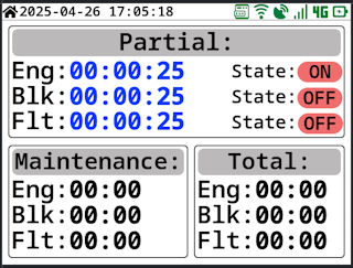
Device Timers
This page shows the current FDR timers values:
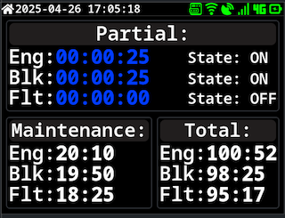
It shows information for three timers:
Eng: Engine ON Time, engine detection based on devicevibrationvalueBlk: Block Time, it starts counting when movement (based on GPS) is detected, it stops counting onEngineOFFand the value will be corrected to when the airplane stop movingFlt: air/Flight Time, based on device Takeoff/Landing detection
The information is show in three sections:
- Partial Timer information
- Shows the current timer (current use block) for engine time, Block Time (start movement) and Air Time
- It also shows each timer state, if they are active or not
- Color Coded:
- Blue: Timers are running (valid as long Engine is detected as
ON) - Orange: Timers are not running (When Engine is detected as
Off)
- Blue: Timers are running (valid as long Engine is detected as
- Timers Values shown as
HH:mm:ss - Timers values are only restarted at
Engine Ondetection.
- Maintenance Timer Information:
- Timers values since last maintenance
- Color Coded:
- White: Default Color
- Red: Maintenance Interval Time has expired
- Orange: Maintenance Interval Time near expiration
- Timers Values shown as
HH:mm
- Total Timers Information:
- Values for each timer since device installation
- Timers Values shown as
HH:mm
The time interval and source for the maintenance timer can be configured and cleared on FlyData platform, by default the time interval is 50h and the timer source used is the Engine Timer.
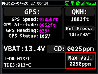
Device Data
Page that shows some sensor / data information from FDR
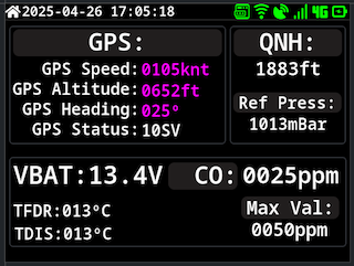
It show information regarding GPS data:
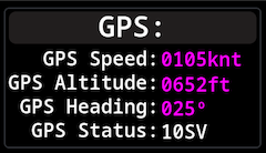
- GPS Speed
- GPS Altitude
- GPS Heading
- GPS Status (Number of satellites used in reception)
In case of no GPS information (No FIX status), all data will be shown with ---
QNH altitude information:
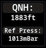
- Current Altitude (based on QNH reference pressure)
- Current Reference pressure
A Long Press on QNH information area, will show up a screen to configure the reference pressure for QNH calculation.
Battery voltage information
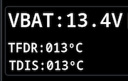
- Battery Voltage, applicable if
FDRis being powered from Power Connector, connected to airplane voltage Bus - Indication of current
FDRandDisplayinternal temperatures
CO Sensor information
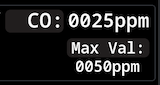
- Current value reading from
FDRinternal CO Sensor - Maximum value registered (since Display powerUp)
It's possible to reset the maximum CO sensor value reading, by Long Press on the Max Val screen area, a confirmation message will show up to confirm the reset of the max value
EFD Page
Page emulating an EFD view, screen generated with recurse to AHRS data
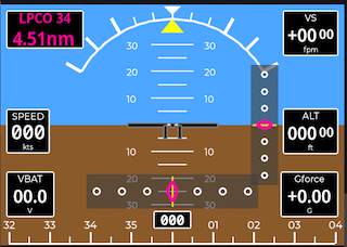
Some of controls shows on screen will depend on current condition, for example the Airport/Runway indication and the Glide/Localizer indicators will only show up if the device is configured with an active vILS procedure.
This screen by default shows:
- GPS Speed
- Battery Voltage
- Red: Battery Voltage below 9.0V
- Yellow: Battery Voltage between 9.0V and 10.5V
- Green: Battery Voltage above 10.5V
- G-Force Value
- Altitude Indication (GPS based)
- Vertical Speed Information
It also shows the artificial horizon, with pitch and bank indication, and current heading (GPS Based).
Some controls only show up if the device is configured with an active vILS procedure:
- Airport / Runway indication
- Top Left Corner
- Glide Slope Indicator
- Right Side of Artificial Horizon
- Localizer Indicator
- Bottom Side of Artificial Horizon
The Localizer Indicator indication works as in VNAV devices, the indicator will show the deviation from the runway centerline, if the airplane is to the left of the runway centerline the indicator will show a deviation to the right, and vice-versa. The full scale if +/-0.3nm from runway centerline.
The full scale deflection depends on distance to touch down point:
- Distance bellow 1nm, full scale +/-0.05nm
- Distance bellow 2nm, full scale +/-0.1nm
- Distance bellow 3nm, full scale +/-0.2nm
- Distance greater than 3nm, full scale +/- 0.3nm
The Glide Slope Indicator indication works as ILS approach, if the airplane is below the glide slope the indicator will show a deviation UP, and vice-versa. The full scale is +/- 1.5° from glide slope.
AHRS Page
Show data information related to AHRS module.
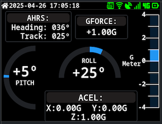
It shows information regarding:
- Pitch Angle
- Bank Angle
- G-Force Value
- Acceleration X, Y, Z
- Magnetic Heading
- True Heading
The AHRS Heading and Track values are only valid when airplane is in movement, otherwise the values may drift over time.
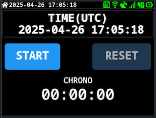
StopWatch Page
Shows a simple stopwatch that can be started/stopped/reset by the user.
vILS Page
Page to show current vILS procedure information.
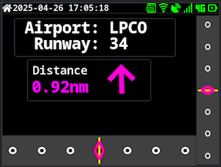
This screen contains information regarding the current active vILS procedure:
- Airport / Runway
- Distance to Touchdown Point
- Direction to Runway
- Glide Slope Deviation
- Localizer Deviation
The scale used for Glide Slope and Localizer deviation is the same as used in EFD page.
If no active vILS procedure is configured the screen will show no data, most fields will show --- and Localizer/Glide slope indicators will not be shown.
Radar Page
Page to show nearby traffic information based on ADS-B data received.
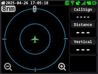
The contents of this page are very similar to FLYsky Display application radar page, with some differences:
- The range can not be changed using the enclosure top buttons, user needs to use
FLYsky Displayapplication to change the range or the onscreen buttons - No
Mode-Starget is shown, only ADS-B targets
This feature should not be used an single source for indication of other aircraft and avoidance maneuvers, the operation of this feature is very dependent on good connection to FlyData servers.
The data shown is acquired in partnership with SafeSky, not all aircraft appear since it's dependent on the aircraft have some sort of active transmitter for it's own position and data aggregators receiver network.
The data shown here is transmitted to the Display via FDR, the data is collected from FlyData server in partnership with SafeSky network and can be complemented by using a local ADSB Receiver such as FDR ADSB Receiver. To avoid large mobile data consumption only targets that are close to the airplane position (and airborne) are transmitted to the FDR, at the moment this is limited to targets within 14nm range from the airplane position with a relative vertical difference of +/-5000ft. maximum of 10 targets (order based in Distance) are sent to FDR. Data is updated when FDR sends its status data to the server, this time interval can vary depending on device current state (airborne/ground) and configuration.
In case a local ADSB Receiver exists, data is updated at 1s interval.
Check Radar Mode User Guide for more information regarding the radar operation.
Charts Page
Page to show some charts with historical data from FDR
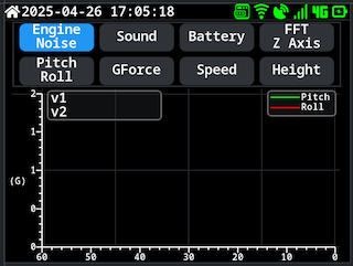
This page allow to show some historical data in chart format, the user can select between the following charts:
- Altitude vs Time
- Speed vs Time
- Engine Noise (Vibration) vs Time
- Sound Level vs Time
- Battery Voltage vs Time
- G-Force vs Time
- Pitch/Roll vs Time
- FFT Data
With the exception of FFT Data all other charts show data with Time in X-Axis and the selected parameter in Y-Axis, the time range is 60 seconds.
For FFT Data chart the X-Axis shows RPM and Y-Axis Amplitude, this chart shows the last FFT data calculated by FDR device, there are two FFT data streams being shown, one based on the Accelerometer Z-Axis data where the amplitude is being shown in IPS scale, and the other is based on FFT Data of the microphone sound level.
Settings Page
Menu page to access Display settings and information.
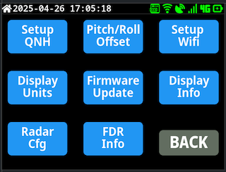
When exiting this page, Display will return to the previous page viewed before entering Settings.
User can exit by pressing the Back button on the bottom right corner or via the shortcut of Long Press on the top left corner time stamp.
Setup QNH
Page to configure the reference pressure for QNH altitude calculation.
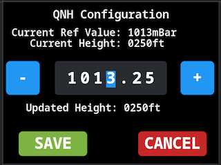
The user can configure the reference pressure in hPa units, valid values are between 750hPa and 1250hPa. By default the increment is done in steps of 1hPa, by pressing the + or - buttons the value will increase or decrease by 1hPa, it is possible to change the increment step by selecting the corresponding digit, the selected digit will be highlighted in blue, pressing + or - will increase or decrease the selected digit.
When incrementing/decrementing the value, it will shown the new QNH Altitude calculated with the new reference pressure.
Press the Save button to save the new reference pressure, or Cancel to exit without saving changes.
Pitch/Roll Calibration
Page to perform Pitch and Roll calibration of AHRS module.
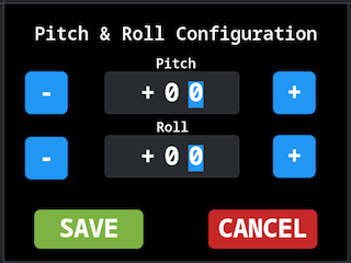
To perform the calibration the airplane must be on a level surface and with wings level.
This menu allows the user to input the new value for Pitch and Roll, these values are used to correct the AHRS readings. Press the + or - buttons to change the values, the values are in degrees format.
Press the Save button to save the new values, or Cancel to exit without saving changes.
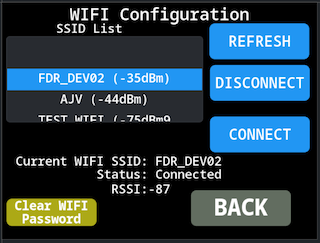
Setup Wifi
Page to configure the Display Wifi connection.
RefreshForce a refresh of the available Wifi networksDisconnectDisconnects from the current used Wifi NetworkConnectConnect to the current selected Wifi Network
It also has indication of the current Wifi network that is in use (in case it has any saved SSID to connect to), and the status of the Wifi.
In case the Wifi Network is password protected when pressing Connect a new screen with a Keyboard to input the password would show up:
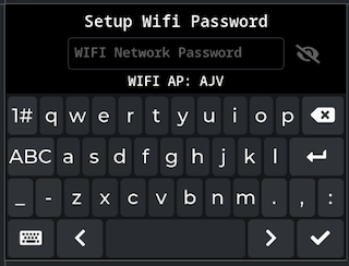
The Keyboard size is kind of small due to the reduced screen size. To return back press the bottom left button and to continue forwarded after inserting the password use the bottom right button. There is a button to show/hide the password near the top right side.
The Display stores the password of the last 5 used network, in case of reconnecting to that network it will reuse the password.
There is a button on the bottom left corner Clear Wifi Password to force the Display to clear the list of used WIFI Networks. It is only enabled if not currently connected to a WiFi Network
The Display will save the Wifi configuration and will try to reconnect to the last used network on next power up. It will also save the last 5 used networks to allow automatic reconnection without the need to input the password again.
Display Units
Page to configure the Display units for different parameters.
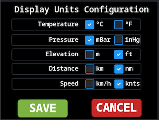
The user can select between Metric and Imperial units for the following parameters:
- Temperature
- Pressure
- Elevation
- Distance
- Speed
Press the Save button to save the new units configuration, or Cancel to exit without saving changes.
Firmware Update
Page to perform Display firmware update.
Check Firmware Update for more information about the Firmware Update process.
Display Information
Page to show Display information, and allows to control display brightness and color theme.

NOTE: There is different behavior between the Back and Save buttons depending on which setting is changed, if the Brightness or the Theme.
In case of Brightness value:
- If the user exit this menu via
BACKbutton, the setting will only persist until the Display reboots - If the user exit this menu via
SAVEbutton, the setting will be stored in internal memory and will be applied on next reboots.
In case of theme setting:
- If the user exit this menu via
BACKbutton, no change to the theme setting is made - If the user exit this menu via
SAVEbutton, the new theme setting will be applied and saved in internal memory to persist in next reboots.
This page also show information regarding Battery status, as well information regarding current firmware version installed and device MAC Address (the MAC Address acts as the serial number of the Display, regarding as device identification for FlyData devices).
Radar Configuration
Page to configure Radar settings.
Check Radar Mode User Guide for more information regarding the radar configuration.
FDR Information
Page to show information regarding connected FDR device.
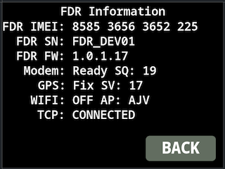
This page shows information regarding the connected FDR device:
- Device Modem IMEI
- Device Serial Number
- Device Firmware Version
- Device LTE Modem Status and Network strength indicator
- Device GPS Status and Number of Satellites used
- Device WIFI Status and current connected SSID (only important if
FDRis connected to server via WIFI) - Device Server TCP Status
System Message
The Display has the ability to show system messages to the user, these messages can be sent from FlyData platform to the Display via FDR device.
When a system message is received the Display will show a popup message:
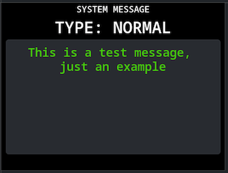
The user can dismiss the message by touching the screen.
There are three message levels:
- Normal Message
- Warning Message, top header in Orange color
- Critical Message, top header in Red color
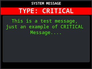
If Warning or Critical message is received the header color will flash between the normal color and a darker color to attract user attention.
The message may disappear automatically after a timeout defined on the message configuration, or may require user interaction to dismiss it, this is defined on the message configuration on FlyData platform.
System Alerts
At the moment the only specific alert the Display shows are related to CO Sensor levels.
There are two warning levels for CO Sensor configured via FlyData platform, one defined as Warning and other as Critical.
When the CO Sensor value exceeds the first warning level a warning message will appear on the Display:

If the CO Sensor value exceeds the critical level a critical message will appear on the Display:
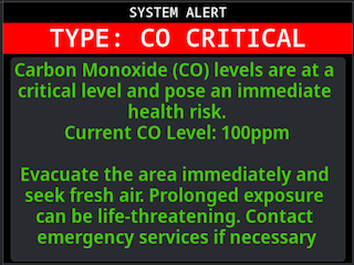
While the alert is visible the header will flash between normal color and a darker color to attract user attention.
User can dismiss the message by touching the screen. It will reappear in case the CO sensor value changes alert level again. In case CO sensor value goes back to normal levels the message will automatically disappear.