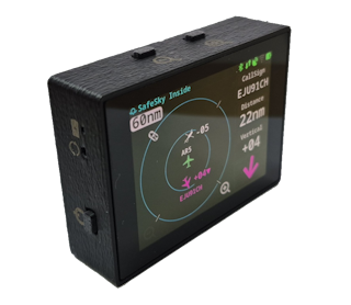
FLYsky Display
The FLYsky Display is designed to receive/display aircraft traffic data from external sources using Bluetooth Low Energy (BLE) data compatible with FLARM NMEA format or Wifi connection using GDL90 protocol.
The Display only shows traffic / Alerts, it does not receive the data signals with ADS-B, FLARM, ADS-L, OGN, etc... it is not an RF receiver, it is necessary to have a RF Receiver (like Aero-Tracker) or an APP on the phone/tablet like SafeSky. The Display also doesn't have a GPS receiver, the GPS data required for operation is supplied from the device/App that is processing the traffic and sending the information.
The Display is intended to enhance the pilot’s ability to see and avoid. Maneuvers to regain adequate separation should not be based on alerts issued by this device or connected applications alone.
This Display is to be used to improve pilot situational awareness only and as a navigational aid. It is not intended for use in IFR flight conditions. FlyData is not responsible for the Display end use and will not be held liable for any events occurring from its use or misuse.
The display is reflective. In very bright conditions, depending on the angle of sunlight, it may become harder to see.
To improve visibility, you can apply an anti-glare screen protector (such as those designed for phones or tablets).
In case of BLE connection, the Display supports two operating modes, one where the Display will connect to an external traffic source (like Aero-Tracker or other compatible device), or the external traffic source will connect to the Display to transmit data (like SafeSky App).
In case of Wifi connection, the Display will listen to GDL90 messages broadcasted on UDP Port 4000 or optionally will also listen to UDP messages on UDP Port 2000 for FLARM NMEA Messages, there is a config option to configure which of the protocols should the display use, see Wifi Supported Protocols .
Although the Display can receive data at the same time via Wifi (either GDL90 and NMEA Flarm) or via BLE (either acting as a client or server) it is advisable to have only one option active at the same time to avoid small inconsistencies between the various data sources that can generate small glitches on the targets present on the screen.
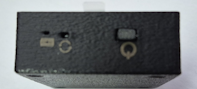
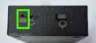
The Display has three external buttons:
- On the side there is the
Power Button - On the top side we have buttons to control the zoom scale on the radar page
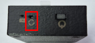
Also on the side where the Power Button is located, there is a small hole to allow to perform a Display Reset, and there is also a LED Light related to battery charging.
In some Displays Screens/Menus there can be a symbol like this one, clicking in it it will show a small help page/text

To connect the Display to SafeSky App, check connecting with SafeSky App, this is the preferable method of use.
To connect the Display to AeroTracker device, check connecting with AeroTracker
Supported Devices
List of devices currently know to work:
| Device | Connection / Protocol |
|---|---|
| SafeSky App | BLE using NMEA Messages |
| SafeSky App | WIFI using GDL90 protocol. Depends on settings on SafeSky App |
| Aero-Tracker | BLE using NMEA Messages |
| Aero-Tracker | WIFI using GDL90 protocol |
| SkyEcho2 | WIFI using GDL90 protocol |
| FDR | WIFI using GDL90 protocol |
| SoftRF Dongles | BLE using NMEA Messages |
In order for the Display to receive traffic from SafeSky App, it is necessary to have a Premium Subscription on SafeSky App.
Display Dimensions
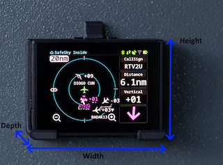
Display is relatively small and light, dimensions are:
- Width: 63mm
- Height: 47mm
- Depth: 18mm
When coupled with the mounting base the dimensions are:
- Width: 70mm
- Height: 51mm (60mm)
- Depth: 27mm
The mounting base has two 4mm holes for support, spaced at 30mm.
Powering the Display
When operating on Battery In order to turn ON the Display press the Power Button for around 2~3s until the screen turns on. To turn OFF the Display press the Power Button for 3s until the Display will turn the screen OFF at that point release the Power Button, while pressing the Power Button an extra symbol will appear on the Display indicating that is detecting the Power Button being pressed.
When using the USB (Type-C) connector, the Display will automatically turn ON and the Power Button will have no effect, after removing the USB cable (if the Display has an internal battery) it is necessary to turn OFF the Display using the Power Button.
The expected battery life is around 10h of use for a full charge battery, the battery life time will be different depending on the external data source and the connection method, the volume of data being received can also have some influence. The selected theme has a big influence in the expected battery life, the 10h is for the default theme Dark, if using the Light theme with 100% brightness the expected battery life reduces to 4h.
The Display Brightness has some impact on battery life, although reduced, between 100% and 40% brightness the power consumption reduces about 10%, a change from 100% to 80% a reduction of maybe 5% with Darktheme. If using the Light theme the reduction of brightness from 100% to 80% for example can give up to 30%~40% of extra battery life.
To maximize battery life time:
- Adjust display brightness to a lower value than 100% if possible. It will depend on atmospheric conditions and Display location inside the cockpit
- Prefer to use BLE connection instead of WIFI connection when possible.
- Disconnect from the WIFI Network in case is out of range. This will avoid the Display to be constantly retrying to connect to the Wifi Network.
- In future versions Display will keep the last Wifi Network password stored even after performing a Disconnect to allow a new connection without having to insert the password again. (Implemented in
1.0.4.0)
- In future versions Display will keep the last Wifi Network password stored even after performing a Disconnect to allow a new connection without having to insert the password again. (Implemented in
In case the Power Button stops responding or the Display firmware is stuck it is possible to force a Reset. On the enclosure side there is a small hole to use to reset the Display, use for example a paper clip to press the button via the hole.
When performing a Reset with the display being powered via battery, the Display will turn off.
Battery Charging
Use a standard phone charger with USB output, the Display has a USB-C receptacle and requires a maximum of 5W while charging.
A complete charging cycle should take around 2h~3h.
On the Display enclosure lateral there is a small LED Light (GREEN) that indicates the charging status:
ONBattery is chargingOFFBattery charging is complete
The current hardware is not capable of detecting in the battery is currently charging and if the charging cycle has completed. The System page may indicate 100% charge and when removing the USB cable the value may drop to 90% (example), when fully charged it should eventually drop to 98%~99% the value is battery dependent.
Power requirements
The Display has an internal battery but it can be powered via USB, the power requirements are:
- While charging, between 3W and 5W
- In Standby (Not charging, display active) < 1W
Display Color Theme
Selection of color theme is only available from version 1.0.7.1
The user can choose between two color themes, Dark and Light, on very "bright" environments the Light theme may facilitate the display visualization. To choose the theme color check Menu Option Display.
| Dark Theme | Light Theme |
|---|---|
 |  |
The display is reflective. In very bright conditions, depending on the angle of sunlight, it may become harder to see.
To improve visibility, you can apply an anti-glare screen protector (such as those designed for phones or tablets).
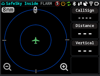
Main Screen
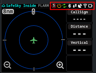
Upon powering the Display the main screen:
On the TOP there are a sequence of symbols to quickly know the current Display state. The symbols (from right to left):
| Name | Symbol | Description |
|---|---|---|
| Battery Level | Indication of Battery Level, color coded: - Yellow: Charging (symbol with extra indication of charging) - Red: Empty (less than 5%) - Orange: Lower than 20% - Yellow: Lower than 40% - Green: Higher than 40% Symbol has “levels” to indicate battery state | |
| Wifi Status | Wifi Status, color coded - Green: Connected to WIFI Network - Orange: Attempting to connect to an WIFI Network - Red: Not connected to a configured WIFI Network - Gray: No WIFI Network Configured | |
| GPS Status | GPS Status, this is the GPS status of the app / source of data to the Display (when connected to AeroTracker indicates the GPS Status of AeroTracker for example): - Green: GPS is FIX - Red: GPS Not FIX (or no data related to GPS) | |
| Data communication | Indication if Display is receiving data from the app / external data source: - Red: No data is being received - Green: Data is being received | |
| Bluetooth | Indication if a Bluetooth connection is active. Either a device connected to the Display or the Display connected to an external device (like Aero-Tracker) - Green: There is a connection active - Red: No connection active | |
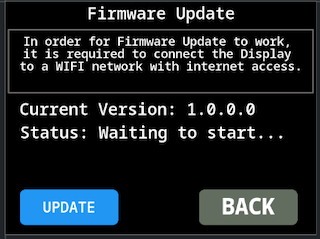
| Firmware Update | Only shown in case there is a firmware update available to the display. Requires connection to a WIFI network with internet access | |
| Power Button | Feedback to user that Power Button is being pressed, only visible while pressing the Power Button | |
| Individual Alerts | Indication that there are “airplanes” configured to ignore collision alert. The number indicates how many “airplanes” have alerts disabled, not visible if no alerts disabled | |
| Global Alerts Disabled | indication that the user has Disabled Global Collision Alerts | |
| Internet Connection | Indication if Aero-Tracker / FDR has LTE Connection. Color will be RED if no internet connection and Green if internet connection available | |
| AeroTracker Battery | Indication of current Aero-Tracker battery level when connected via BLE. |
On the Top Left side there two text indications reflecting the current operating mode / data source type:
SafeSky Insidehighlighted by default, it means the Display is setup to receive data from SafeSky App, this means the alerts are managed from SafeSky AppFLARMhighlighted if Data Source is defined as “Compatible with FLARM”
On the Main Screen there are also two buttons to control the radar zoom level.
It is also possible to control the Zoom via gestures, by making UP and Down swipe gestures.
The on screen buttons can be disabled.
The Display supports radar scales of 1nm, 2nm, 4nm, 8nm, 10nm, 20nm, 40nm and 60nm. (Or 2km, 4km, 8km, 15km, 20km, 40km, 80km and 120km if the device is configured to use km as units for distance)
Indication of No Internet Connection
In case the Display is connected to SafeSky APP via BLE, if the phone/tablet that is running the app looses internet connection, a popup will show up on the Display as a warning.
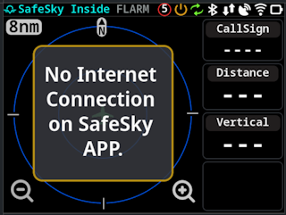
This warning/popup will only appear if Display is configured to work with external data source of type SafeSky App.
A similar warning will also show when Display is connected to FDR and it has lost internet connection
Aero-Tracker specific extra indications
Internet Connection Status
The indication of internet connection for Aero-Tracker is only available starting in version 1.0.6.1, and only if connected to Aero-Tracker via BLE.
In case of Aero-Tracker devices, an extra symbol will appear on the symbol row to indicate internet connection status (The popup is not used since Aero-Tracker does not require internet access to receive data, internet data is used as means to get extra data).
![]()
The symbol will have the color RED when Aero-Tracker reports no internet connection and Green when it has internet connection. This indication is dependent on Aero-Tracker to send Status message via BLE.
Battery Status
The indication of Battery Status for Aero-Tracker is only available starting in version 1.0.6.2, and only if connected to Aero-Tracker via BLE.
When connected to Aero-Tracker via BLE, the Display will show the current Aero-Tracker battery level on the symbol row, the indication will battery capacity together with a color coded border depending on battery level.
![]()
The battery symbol will have different border colors depending on the battery level:
- Green: Battery level higher than 75%
- Yellow: Battery level between 50% and 75%
- Orange: Battery level between 20% and 50%
- Red: Battery level lower than 20%
FDR specific extra indications
FDR - Internet Connection Status
In case of FDR devices, an extra symbol like for Aero-Tracker will appear on the symbol row to indicate internet connection status.
![]()
The symbol will have the color RED when no internet connection and Green when it has internet connection. This indication is dependent on FDR connection status with the server.
The no internet popup will show in case FDR does not have internet connection and no local ADSB receiver is paired with FDR.

Main Screen - Radar Operation
Normal view of the Display with traffic in the radar screen.
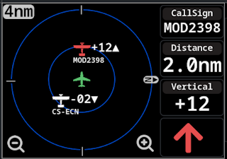
By default Display has no idea of own airplane CallSing (ICAO ID), so if the data receiver that is supplying data to the display is not correctly configured the Display may show it's own "position" as a "target" and generate alarms to it's own CallSign, check configuration option Setup Airplane ID
On the right side the display will show information of the nearest target, including device CallSign (will show empty if target is in private mode), distance to target, relative vertical difference (in hundreds of feet) and an arrow pointing in the direction of the target. The Arrow/Display assume that the display is facing the travel “direction”.
Next to each target on screen it is also shown the vertical difference (in hundreds of feet) as well the device CallSign. There are config options to control how this information is shown next to a target, see Vertical Decluttering and Radar Decluttering configuration options.
| No Screen Decluttering options disable | All Screen Decluttering options enabled |
|---|---|
 |  |
The UP symbol that appears on the relative vertical altitude information, only shows if target is reporting ClimbRate.
The data source may already be implementing some configurations regarding screen decluttering. For example SafeSky App already only sends information to the Display based on the filters defined in the App.
Currently there four possible colors for the targets, depending on configuration:
- White: Normal status color, is the one used by default
- Light Blue: Indication that the target is “Grounded”, only visible if enabled in config
- Light Gray: Indication that the alert for that target is disabled
- Purple: Indication that is the nearest aircraft (it will switch to white if display in alert status)
The display shows an indication where North is located, this indication (and the Display following current heading) is only valid/shown when the GPS speed reported is higher than zero, be noted that the device/data source that is supplying the data may have some internal behavior regarding this, in flight condition the display will follow the airplane orientation and the data presented on the display should be accurate with the current travel heading.
The Display will block the heading to 0º if GPS speed reported is lower than 4Kmh. When connected to SafeSky App via BLE NMEA the display will show the heading according to the Phone/Tablet magnetic heading.
The Displays support a couple of symbols for Targets depending on how the target is being identified on GDL90 or NMEA Message. At the moment the following symbols are present:
| Symbol | Description |
|---|---|
| Generic symbol for when the target type doesn’t have a specific symbol. Also shown for “Small Aircraft” | |
| Symbol for “Helicopters” | |
| Symbol for “Drones” | |
| Symbol for “Military” | |
| Symbol for "Jets" / "Airliner" | |
| Symbol for "Glider" | |
| Symbol for other “Glider” type (ParaGlider, HandGlider, etc...). |
More symbols may be added in the future.
MODE-S Aircraft
The Display can show targets that are only transmitting Mode-S information, this works in case the device is receiving traffic data using FLARM NMEA protocol, tested with AeroTracker.
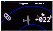
When receiving information for a Mode-S target, the radar page may look like this:
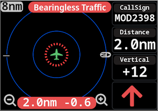
There are configuration options to enable/disable the two "bars" popups that show indication of "Bearingless Traffic" and "Distance and Relative altitude" information, as well an option to disable the "Distance circle" presented on the radar around "our airplane" and to show only if closest target.
In case this target is the nearest one, the "arrow" that appear on the right bottom side will disappear and is replaced by an "Exclamation Mark" (![]() ) since the Display doesn't know it precise location, if there is a regular target nearest it will show the arrow as normal.
) since the Display doesn't know it precise location, if there is a regular target nearest it will show the arrow as normal.
The distance presented on the Display is calculated by the device that is receiving the Mode-S signal, this value can be very inaccurate since it depends on RF signal reception quality, antenna placement, target aircraft orientation etc...
The Display only shows information for one Mode-Starget, if more than one exist at the same time only the information for the nearest Mode-S target is shown.
Disabling Alerts
It is possible to disable alerts to a specific target, in order to do that click on the target symbol and a popup will show up to confirm the action.
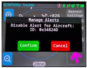
In case the action is Confirmed that target will show on the radar page with a different color (Light Gray):
The user can re-enable the alerts for the target by clicking again the target symbol on the screen and confirming the action, or going to “Settings / Alerts” and managing the option there.
Alerts
The Display will show visually alerts on screen, the following examples represents how the alert is displayed for each level (based on SafeSky App).
When the Display detects an alert situation, the Radar scale will be automatically adjusted based on the distance to the target on alert status. The user can override this “zoom”, the scale is only adjusted once per alert.
Display has no idea of own airplane CallSing (ICAO ID), so if the data receiver that is supplying data to the display is not correctly configured the Display may show it's own "position" and generate alarms to it's own CallSign
In case of alert status, the information shown on the right side is always related to the target that triggered the alert, and not the “nearest” target.
The behavior explained is for when the data source is set to SafeSky App but it is similar when using other types of sources or the alerts are generated internally.
Alert Level 1 - Caution
This alert is generated by SafeSky App if a “collision” may happen between 45s and 90s, in this case the app changes some colors to “blue” and start signaling the target:

The Target “border” will blink.
Alert Level 2 - Warning
Alert generated by SafeSkyApp if a “collision” may happen between 25s and 45s:
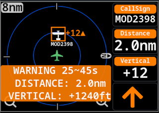
The target “border” will blink, and the popup on the bottom will also blink.
The popup location will depend on the target position on screen.
Alert Level 3 - Danger
Alert generated by SafeSkyApp if a “collision” may happen in less than 25s.
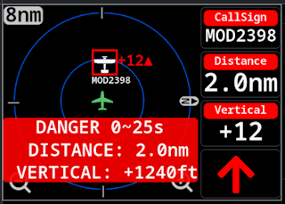
The target “border” will blink, and the popup on the bottom will also blink.
The popup location will depend on the target position on screen.
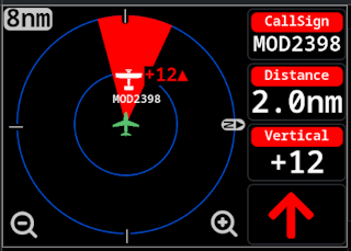
Alternative method to visualize alerts
Depending on configuration options, (This is the new default since version v1.0.5.0) it is possible to disable the popup and instead show a highlight area to indicate the position / orientation of the airplane that triggered the alarm.
Alerts when using FLARM
When using FLARM as the source the alerts will behave as follows:
- Alert Level 1
- Time to Collision 15s~20s
- Color: Yellow
- Popup is shown
- Alert Level 2
- Time to Collision 10s~15s
- Color: Orange
- Popup is shown
- Alert Level 3
- Time to Collision less than 10s
- Color: Red
- Popup is shown
Alerts generated by display
When the display is configured to generate the alerts internally:
- Alert Level 1
- Time to Collision 30s~60s
- Color: Yellow
- Popup is shown
- Alert Level 2
- Time to Collision 15s~30s
- Color: Orange
- Popup is shown
- Alert Level 3
- Time to Collision less than 15s
- Color: Red
- Popup is shown
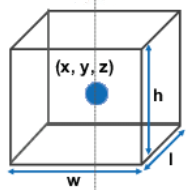
The Display generate collision alerts based on the target current position, altitude, speed, heading and ClimbRate and it's own position, altitude, speed, heading and ClimbRate, it then calculates the new positions for the next 60 seconds for booth target and Display, if the target is inside a bounding box surrounding the Display/Aircraft an alert will be triggered, the alert level will depend on time to intercept.
The bounding box is currently defined as a "box" with display centered with 200m in length (l) and width (w) and 100m vertical height (h).
Settings Screen
To access Settings press the icon area (top right of the Display) for around 0.5s, a new page will show up:
There are several buttons to access device configuration.
It is also possible to access the settings by making a short click on the power button, the short click must have a duration between 50ms and 0.5s.
Only valid form firmware version 1.0.1.0 and onwards
Menu WIFI
Allows to connect the Display to an Wifi network. In normal circumstances this will only be used for Display Firmware Update, although the Display can connect for example to the AeroTracker Wifi network to receive data via GDL90, there are some “details” regarding GDL90 support, see Wifi Supported Protocols
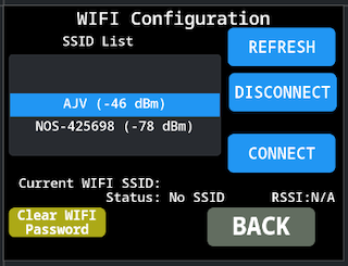
RefreshForce a refresh of the available Wifi networksDisconnectDisconnects from the current used Wifi NetworkConnectConnect to the current selected Wifi Network
It also has indication of the current Wifi network that is in use (in case it has any saved SSID to connect to), and the status of the Wifi.
In case the Wifi Network is password protected when pressing Connect a new screen with a Keyboard to input the password would show up:
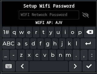
The Keyboard size is kind of small due to the reduced screen size. To return back press the bottom left button and to continue forwarded after inserting the password use the bottom right button. There is a button to show/hide the password near the top right side.
The Display stores the password of the last 5 used network, in case of reconnecting to that network it will reuse the password.
There is a button on the bottom left corner Clear Wifi Password to force the Display to clear the list of used WIFI Networks. It is only enabled if not currently connected to a WiFi Network
Up until version v1.0.6.0 only the last wifi network password was saved, only after this version it started to store up to 5 WIFI networks passwords.
Menu Bluetooth
Similar to the Wifi Menu, it allows the Display to connect to external bluetooth devices. This menu is to connect to external devices like AeroTracker, in case the Display is connected via Bluetooth to SafeSky app, that will not be indicated on this Menu.
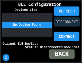
The Display supports Bluetooth devices that are advertising support for BLE Service UUID 0xFFE0, supported (tested) devices are:
- Aero-Tracker
- SoftRf devices (tested on
Prime Edition MkIIIwith firmware version1.7.1and the NMEA output set to BLE).
The buttons behavior is similar to the Wifi menu:
RefreshForce a refresh of the available BLE devicesDisconnectDisconnects from the current used BLE DeviceConnectConnect to the current selected BLE Device
It also has indication of the current BLE Device that is in use, and the status of the BLE connection.
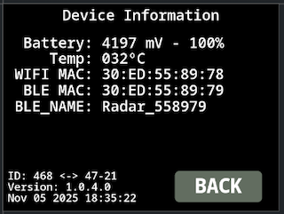
Menu System
Visualize some internal information of the Display such as Battery level/voltage, Temperature, MAC Address and firmware version.
Menu Firmware
Allows to update the firmware of the Display, the behavior will be explained in a separated page .
Menu Display
This menu changed from firmware version 1.0.2.0, now it allow to save the setting, before that the setting was not persistent (would restore default after a reboot)
From version 1.0.7.1 it allows the user to select the display theme color.
Allows the control of the Display Brightness and select the theme color.

NOTE: There is different behavior between the Back and Save buttons depending on which setting is changed, if the Brightness or the Theme.
In case of Brightness value:
- If the user exit this menu via
BACKbutton, the setting will only persist until the Display reboots - If the user exit this menu via
SAVEbutton, the setting will be stored in internal memory and will be applied on next reboots.
In case of theme setting:
- If the user exit this menu via
BACKbutton, no change to the theme setting is made - If the user exit this menu via
SAVEbutton, the new theme setting will be applied and saved in internal memory to persist in next reboots.
It can be useful in case of taking photos or videos of the Display to reduce the brightness to around 20~30% otherwise the colors on the phone camera may appear over saturated, this behavior depends on phone/app default settings. With the Light theme when taking photos, depending on app settings it is possible to catch the Display scanning/refresh sequence.
Menu Alerts
Using this menu the user can control some aspects of the alerts the display generates/shows to the user.
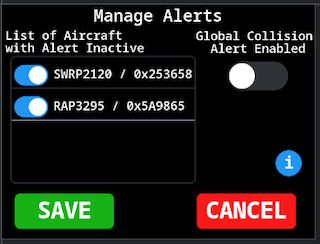
There is an option Global Collision Alert Enabled that if disabled the Display will not generate alerts for any target. When this option is enabled, the following symbol will appear in the symbol area:
![]()
And is also possible to manage individual alerts for specific targets. In this menu it is only possible to reactivate the alerts for a specific target, to disable alerts for a specific target is done in the main Radar Screen.
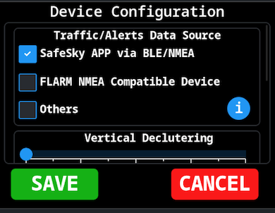
Menu Config
This is the main config menu for display functionality / behavior.
These settings values are stored in Display internal memory and will persist upon PowerUp / reboots.
Is composed of several sections.
Traffic/Alerts Data Source
Defines the type of data source that is connected to the Display, this will change the behavior related to collision alerts generation.
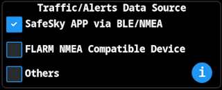
SafeSky APP via BLE/NMEA- Select this option if using SafeSky App, in this case the collision alerts shown on the Display will be the same as in SafeSky App and will follow the same color schema / alert level
FLARM NMEA Compatible Devices- Select this option if using an external data source (like SoftRf dongle) that are sending the data using NMEA FLARM spec and are also generating the collision alerts (SoftRf has that ability).
Others- Using this option the collision alerts will be generated internally by the display ignoring the external data source in that respect. The display will calculate the collision risk up to 60s ahead and generate an alert level based on time to “impact”.
- In case of using AeroTracker, at the moment is necessary to select this option, since at the moment AeroTracker does not generate alerts.
Vertical Decluttering
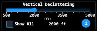
By default the Display will show traffic sent by the external data source that has a relative altitude difference of +/-1000ft, but it allows the user to change this setting, there are two options:
- Adjust the vertical difference between display position and target position, to only show targets with relative altitudes between 500ft and 5000ft (100ft increments), the user can select the value.
- Or enable the option
Show Allin order not to perform any kind of filtering based on vertical difference.
This setting can have little effect, depending on the data source.
SafeSky App for example only sends to the Display what is visible on the APP Radar View that is already influenced by internal APP filtering related to Vertical Decluttering setting in the APP (up to +/-5000ft), so even if the Display has Show All if the APP is setup to +/-1000ft only targets up to +/-1000ft will show up.
Other Data Sources may have similar filtering, Aero-Tracker as a similar internal filter for targets that are received via SafeSky LTE Connection, these filter does not seem to apply to ADSB/ADS-L targets received directly by it.
Radar Decluttering
Used to reduce the amount of information that is displayed in the radar page.
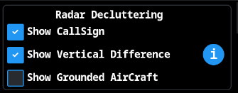
Show CallSignIf it should show the target CallSign on the radar page next to the target.Show Vertical DifferenceIf it should show the vertical difference between the Display and the Target in numeric format.- If this option is disabled, the Display will show an
+or-sign, depending if the vertical difference is positive or negative
- If this option is disabled, the Display will show an
Show Grounded AirCraftIf the Display should show on the radar page grounded aircraft, grounded aircraft will show on the radar page with aLight bluecolor.
The next image shows an example of a target on radar page with the default settings (Show CallSign and Show Vertical enabled):

The next image shows an example of a target with booth options disabled:

The Show Grounded Aircraft when disabled, will hide from the radar page (and alert collision calculation) that is reported by the data source as being grounded, GDL90 has a specific field for that and should work OK, but NMEA the indication that a target is grounded is by sending the speed at 0Kmh, this can cause some issues with UAV and/or Helicopters for example.
When using SafeSky App as the data source, this option is not useful since SafeSky App only sends to the Display traffic that it considers to be Airborne.
The arrow on the Vertical Difference indicates the target reported ClimbRate. if the reported ClimbRate is 0 the arrow will not show
This functionality was changed in version 1.0.2.0 before the arrow / sign did not show up when disabled, only a single arrow would show to indicate above/bellow
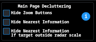
Main Page Decluttering
Allows to hide the Zoom buttons and also to hide the information related to nearest target (information on the right side panel).
Where:
Hide Zoom Buttons: To hide the zoom buttons from the radar screen.- It is still possible to change the zoom level via the physical buttons on the Display enclosure or using swipe gestures on the screen.
Hide Nearest Information: The information shown on the right side panel related to the nearest aircraft will not be shown.- The
Arrowwill still be shown, to indicate the nearest aircraft orientation - In case of
Alertthe information related to the alert aircraft will be shown
- The
Hide Nearest Information: Second option, will hide the information on the right side panel, it the receiving nearest target is outside the radar scale / not visible on the radar page.
Alerts Visualization
Control some aspects of alerts.
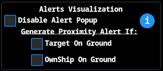
If option Disable Alert Popup is Active the popup will not show and instead it will show a highlighted area.
With Disable Alert Popup Active | With Disable Alert Popup Inactive |
|---|---|
 |  |
From firmware version 1.0.5.0 this option is now by default active. It does not show the Popup only Highlights the target direction area.
The other two options control alert generation
Target On GroundIf active, Display will generate alerts for traffic that are considered as being on Ground.- In order for this detection to work the option
Radar Decluttering/Show Grounded Aircraftmust be enabled - If using
SafeSky Appas the data source, this option as no effect since it only sends to the Display traffic that is considered to be AirBorne, - For other sources, the detection if a target is
OnGroundis done based on the speed field on NMEA message, if the value is0is considered as on Ground,GDL90has a specific field for this information.
- In order for this detection to work the option
OwnShip On GroundIf active, Display will generate alerts even if the Display considers to be atGround- In case of data source is sending information via
NMEAmessages, the Display considers that isOnGroundif reported GPS speed is lower than 8Kmh - In case of data source is sending information via
GDL90messages, the specific field in the message is used.
- In case of data source is sending information via
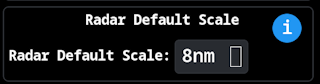
Radar Default Scale
Only available from firmware version 1.0.2.0
Allow the user to set the default radar scale the device uses after power Up.
Mode-S Options
Allows the user to control what is shown on the radar page for a Mode-S target.
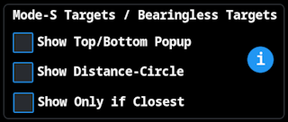
Show Top/Bottom Popupif it will show the Top/Bottom popup bars with target information and indication that is seeing aMode-S/BearinglesstargetShow Distance/Circleif it shows the dash circle centered on the Display Radar map with indication of expected distance to targetShow Only if Closestif enabled, will only showMode-S/Bearinglesstarget indication it it's the closest target.
Mode-S targets distance is typically calculated based on RF Signal strength, this method can lead to some substantial distance errors.
By default all options are enabled.
Mode-S target visualization at the moment is only validated when using Aero-Tracker as the Data Source and it is connected to the Display via BLE.
Device Units
Allow the user to change the default units used to indicate distance and altitude.
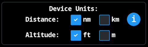
Even if the altitude is set to meters the relative altitude shown next to the target and in the right side panel is always in hundreds of meters
Wifi Supported Protocols
Setup which protocol the Display will support when connected via Wifi to an external traffic source.

When using Wifi there are two possible protocols to get data from, NMEA or GDL90, booth can be active at the same time the Display will merge the data based on the target ICAO ID but since this can lead to some “glitches” on the radar page it is advisable to only have one protocol enabled at a time.
NMEA protocol is supported by listening to UDP messages on port 2000, this is the implementation that Aero-Tracker uses.
GDL90 protocol is supported by listening to UDP messages on port 4000.
Display is expecting to receive the following GDL90 messages in order to properly operate:
- HearBeat message Code “0”
- OwnShip Report Code “10”
- Traffic Report Code “20"
If the data source is not sending these 3 messages codes the Display will not operate properly.
In firmware version 1.0.0.0 it is mandatory to have at least one protocol selected, this will be removed in the next version
Restore Defaults
User can use to restore the display to it's default factory settings.

A popup will show up to request the user to confirm the operation.
These default settings do not include the Wifi Network selected/connected, and also do not include the Bluetooth device that may be paired/connected with the Display.
The device default settings are:
| Configuration | Default |
|---|---|
| Traffic/Alerts Data Source | SafeSky App |
| Vertical Decluttering | Limit to +/-1000ft |
| Screen Decluttering | Only Show CallSign and Show Vertical Difference are enabled |
| Main Page Decluttering | All options disabled |
| Alerts Visualization | Only option Disable Alert Popup is enabled |
| Mode-S Target | Show Top/Bottom popup, Distance/circle are enabled and Show Only if Closest enabled |
| Wifi Protocols | Only NMEA is enabled |
| Altitude Units | Feet |
| Distance Units | Nautical Miles |
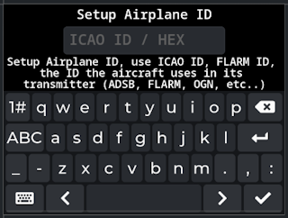
Menu Airplane ID
Allows the user to configure the aircraft ID to allow the Display to filter traffic information from own aircraft.
- Use the bottom right keyboard button to
accept / savecurrent value - Use the bottom left keyboard button to
exitthe menu without changes.
This configuration is not normally necessary, since the device that is acting as Data Source normally has this already filtered, it is just an option in case of some misconfiguration on the Data Source.
The ID to use, must the transponder ID the aircraft uses, either be ICAO ID, FLARM ID, OGN ID. The ID must be entered in HexaDecimal format, maximum of 8 digits.
In order to remove the current ID and clear this configuration, just input the number 0 and save the configuration.