FDR installation Manual
There are three product variants of FDR, this manual serves for all product variant.
Product Variants
| Model | Description |
|---|---|
| FDR1A | FDR Base model, GPS antenna internal (no external connection), with LEDs and Display |
| FDR2A | Same as FDR1A but with connection for external GPS Antenna |
| FDR3A | GPS Antenna external, no LEDs, Display and Knob |
Product Size
FDR box as a base size of 131x100x30. The height is just the enclosure height, final height will depend on mounting option and final dimensions/space used will depend on antenna mounting options.
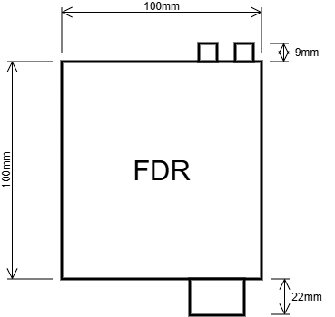
The enclosure has two mounting holes on the bottom for M3 screws.

The maximum depth FDR has for M3 screws internally is 5mm, any longer than that you risk damaging internal PCB.
By default FDR has the Garmin mounting accessory coupled, it can be removed
Front Panel
Only for products variant FDR1A and FDR2A.
FDR3A product variant don't have any features on the front panel.
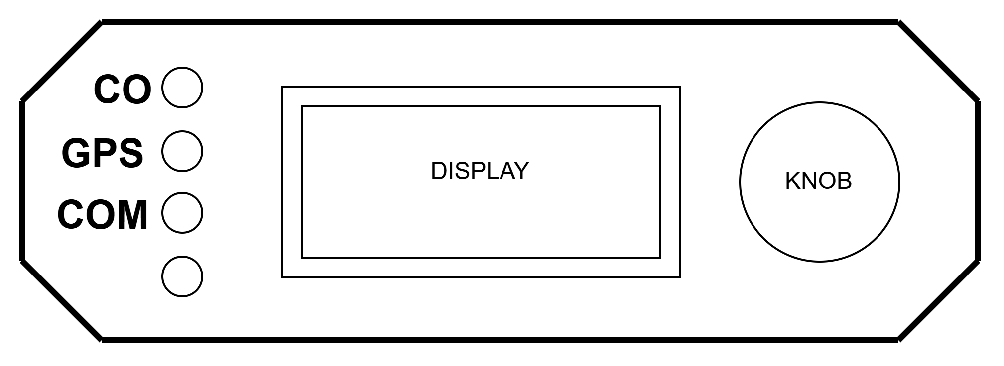
The front panel is composed by:
- 3 LEDs on the left side
- From TOP to Bottom
- CO Sensor Status
- GPS Status
- Server communications Status
- From TOP to Bottom
- Light Sensor on the left side (bottom)
- Display
- Encoder Knob
The Leds have the following states:
- CO Sensor
- Green: Sensor values OK, low value
- Orange: Sensor values higher than medium level alarm
- Red: Sensor values higher than danger level alarm
- GPS
- Green: GPS Status is OK (Fix State)
- Blue: GPS waiting for Fix
- Orange: GPS has Fix, but Satellites number is Low
- Server Communication status
- Green: FDR is connected to server
- Blue: LTE modem is not registered, waiting for network
- Orange: LTE modem is registered, but it is not connected to Server
The Leds intensity and display brightness are automatically dimmed according to the light sensor value readings.
The Display and Knob are explained in the user manual.
Back Panel
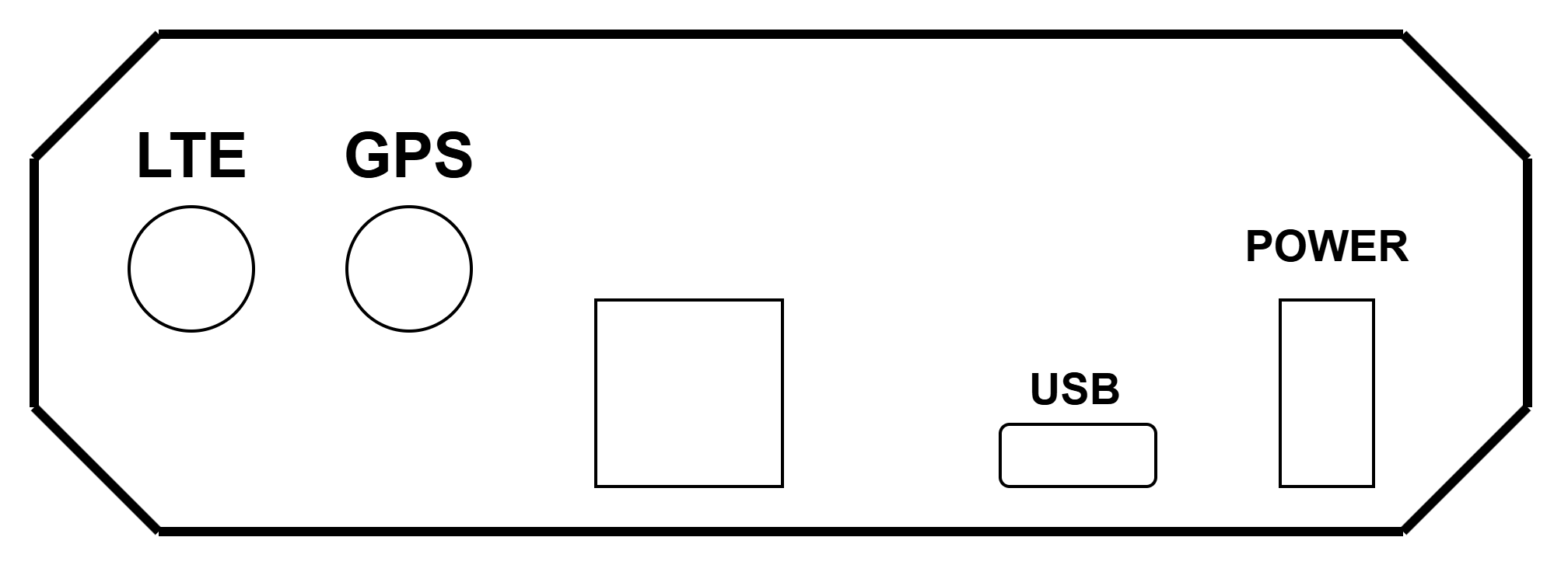
On the Back Panel we have:
- SMA Connector for LTE Antenna
- SMA Connector for GPS Antenna
- Expansion connector
- USB Type C Connector
- Power Connector
GPS Antenna connector is not available in all versions. Version FDR1A does not have this connector since the GPS Antenna is internal to the equipment.
Power Connector
Power connector is a Molex Micro-Fit connector
- Cable connector housing part number: 0430250200
- Pins: 430300001 (20 to 24AWG) and 430300007 (24 to 20AWG)

Where:
- Pin 1 -> VCC (8V~34V)
- Pin 2 -> GND
Expansion Connector
Expansion Connector to be used to connect to external peripherals, it supports an RS232 (TTL Level) communications link, or two Digital/Analog inputs.

Where:
- GND (0V)
- Comms Signal
- Comms Signal
- Power (+5V)
Antenna Connector
Generic SMA Female antenna connector.
Use the antennas provided in the installation box.
Powering FDR
FDR supports being powered via either USB Connector or by the Power Connector.
The preferable method is using the Power Connector with a connection to the aircraft main bus voltage.
When installing FDR if possible FDR should be placed in it's own circuit breaker (1A) or put in one non-critical system.
Do not install FDR without connecting via a circuit breaker or at least a fuse. Use a fuse of 1A minimum. The default power cable already contains a 1A fuse.

Supply characteristics
When using Power Connector:
- Voltage: From 8V to 34V
- Power: Up to 5W during first 3 minutes after power on, less than 3W after 3 minutes.
When using USB:
- Voltage: 5V +/-0.2V
- Power: Less than 5W
FDR should be compatible with most USB Chargers available in market, either with a USB-A to USB-C cable or USB-C to USB-C cable.
It's possible to power FDR via a Power Bank using the USB connector, be advised that since the power consumption is relatively low, some power banks may auto-disconnect the power output if power being draw is too low.
Do not power the device via USB Connector with more than 5V, risk of damaging the equipment
Mounting
The location to install the equipment will vary depending on the model purchased and aircraft configuration.
Some recommendations:
- Install
FDRin the correct orientation- The
FDRBack Panel(Antenna and power connector) must be direct to the front of the airplane - Try to have keep
FDRaligned with airplane frame.
- The
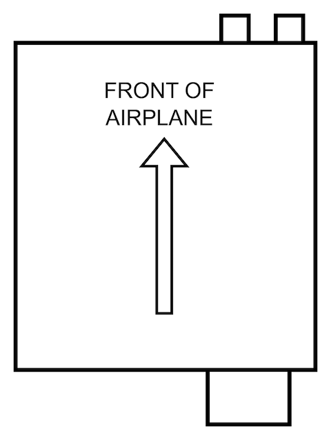
- Try to install FDR as leveled with the airframe as possible
- Try to avoid an offset greater than 5º (Either Pitch or Roll)

- If the device has internal GPS Antenna (Variant
FDR1A) theFDRmust be installed in a location where it has a clear view of the sky
- If the device has external GPS Antenna, the device can be placed inside the instrument panel for example, but make sure the external GPS is located somewhere with a good and clear view of the sky.
- In case of using the Extension external LTE antenna, place it somewhere relative away from metallic pieces and 10~15cm away from other transmitting antennas
There various options to mount the equipment:
- Use the
Garminstyle mounting support supplied in the product box - Use velcro to place it in a flat surface, use a strong velcro, a patch size of at least 70% of FDR Area
- Use double sided adhesive, thinner adhesive is recommended, use a patch size of at last 70% of FDR Area
- Fix FDR to a metallic surface / support structure using the two M3 mounting holes on the device
- NOTE: The M3 screw maximum length on FDR enclosure is 5mm
The maximum depth FDR has for M3 screws internally is 5mm, any longer than that you risk damaging internal PCB.
By default FDR has the Garmin mounting accessory coupled, it can be removed
Validation after installation
After installing the device, power it on and check it's status.
If a variant with Display and LEDs, check the LED status (in case the device is visible), otherwise use the FDR Display Installer to validate the installation conditions.
Do a check, and verify that FDR does not interfere with other avionics equipments.
Information to give FlyData
After installing an FDR on an aircraft, please send the following information to FlyData in order to create the device on the web platform:
- FDR Serial Number
- Aircraft Manufacturer and Model
- Aircraft Registration Number
- Aircraft Transponder code (ICAO 24 Bit Code)
- If not using the
FDR Display Installerto calibrateAHRSmodule:- Indicate expected Pitch and Roll values (check in other avionics equipments) when aircraft is on Ground