FDR User Manual
User manual related to the FDR Internal display usage.
In order for FDR to work properly make sure the GPS antenna has good sky visibility and that it is properly fixed
The Display is composed by several menus/screens, the navigation between the menus is done by rotary encoder. Access sub-menus is done by Long Press on the encoder, selection and/or exit from sub-menu is done by Short Press on the encoder.
The device Screens are in "carrousel" with the exception of the two first screens, one with the product logo and one with a navigation warning.
-7863a2ef24c8908b4b457271492ef12b.png#center)
Navigation Control
- To navigate between main menus, just use the rotary encoder, right-left will navigate the menus in the sequence on diagram above
- To access configuration menus, move to the corresponding menu page and
Long Pressthe encoder until the system change to the respective configuration page - To exit the configuration menu (unless otherwise stated bellow),
Short Pressthe encoder.
Screens
Partial Time
Presents the current block/partial time counter.

The device keeps time tracking for three separated counters:
- Engine Time
- Block Time (since the airplane start moving)
- Flight Time
The times values are color coded, Blue means the timers are enabled and counting, Orange means the timers are disabled, stopped counting.

The timers change to enable as long as an Engine On is detected and pass to disabled when an Engine Off is detected, this controls the global behavior, each timer counts it's time independently but the Engine timer is the master control.
Maintenance Timer
Present to total time elapsed since last maintenance.

If the timer values are Orange it means the airplane is close to it's maintenance time period, if Red it has overshoot the maintenance interval.
It's possible to configure on FDR which timer source is used as the base time for the maintenance interval, and also the maintenance interval duration (in hours)
Configuration done via FlyData platform.
CO Sensor
Indication of current CO sensor value and the max value recorded since last device boot.

Clock
Indication of current UTC Time (GPS Synchronized)

GPS Information
Information related to GPS Status

This page shows:
GPS Altitudein feetGPS StatusGPS SatellitesNumber of satellites used by GPS module, should be higher than 10 in standard conditions.GPS Speedin knots
In case no GPS Fix has been made, the values will be shown as ---
GPS Track
Indication of current GPS Track.

In case no GPS Fix has been made, the values will be shown as ---.
This value may not be correct if airplane is stopped or at very low speed.
Altitude QNH
Indication of current QNG altitude and reference pressure used to calculate it.

Calibrate Altitude QNH
It is possible to calibrate the reference pressure used to calculate QNH Altitude.
Long Presson the encoder while in Altitude QNH page until a new screen shows up

- Use the rotary encoder to control the reference pressure
- The
QNHvalue will change accordingly (and change toOrangeto indicate that has changed)
- The
- In order to save the new reference value,
Long Presson the encoder until the system exists the menu and return to previous page
To exit the menu without saving the new value, just Short Press the encoder
G-Force Value
Indication of current G-Force value measured by FDR

AHRS Pitch/Roll
Indication of current Pitch and Roll being measured by AHRS system.

In case the system is still in the initialization phase, or the GPS data is not good enough will show:

Pitch and Roll Calibration
It is possible to calibrate the Pitch and Roll offset values.
Perform a Long Press on the encoder while in the AHRS Pitch/Roll page, until a new page is shown

When entering this new page, it is possible to set the new value for Pitch. To switch to the Roll perform a Short Press on the encoder.

After that, a new Short Press will exit the menu and apply the values.
AHRS Heading/Track
Indication of the current Heading/Track being measured by AHRS system

In case the system is still in the initialization phase, or the GPS data is not good enough will show:

These values are only valid if aircraft speed is higher than 5knt
Menu Information
Indicates the FDR current voltage supply value and internal temperature.

- There is an indication of the current voltage source:
BATFDR is being supplied via the main power connector / Aircraft batteryUSBFDR is being supplied via USB connectorCAPFDR is being supplied via internal Ultra Capacitor (it only has capacity to support FDR for around 30s, is mainly to finish communications with the server and report that it has lost power)
Extra Menu Information
When in the screen Menu Information it is possible to access more details about FDR status. Long Press the encoder until the system change page and there is a new sub-screens with several information
| Screen | Description |
|---|---|
 | FDR LTE Modem IMEI |
 | FDR Serial Number |
 | Information about LTE Modem Status |
 | Information about TCP Server connection status |
 | Information about FDR WiFi connection status |
 | Information about FDR Firmware Version |
Virtual ILS
The correct operation of this functionality is dependent on GPS, user configuration and TCP server connection
Presents a virtual ILS screen.

It presents:
- Airport Code and runway code
- Orientation for Airport
- Distance to Airport
- Glide Slope Indication
- Total scale -1.5º / +1.5º
- Localizer Indication
- Total scale -1.5º / +1.5º
In newer firmware versions, the Localizer indication is no longer the angle deviation to localizer point, but the lateral distance to the ideal path to localizer center line (similar to LNAV)
The full scale deflection depends on distance to touch down:
- Distance bellow 1 nm, full scale +/-0.05 nm
- Distance bellow 2 nm, full scale +/-0.1 nm
- Distance bellow 3 nm, full scale +/-0.2 nm
- Distance greater than 3 nm, full scale +/- 0.3 nm
The device will jump automatically to this screen when entering an ILS Zone, if the user exit this menu via rotary encoder the device will not return automatically until it Exist/Enter a new ILS Zone.
vILS configuration
The option to select a runway is deprecated in newer firmware versions. The server configures the nearest runways to the aircraft position, since this configuration is now dynamic the option to pre-select an airport/runway was deprecated.
The virtual ILS can operate in two modes, automatic or user select runway.
In automatic mode, FDR will select the runway automatically based on the internal airports/runways, if inside the ILS zone (lower than 4000ft above runway elevation, and in area preceding the touch down zone) it will select that runway.
In automatic mode, the runways list will be automatically updated via communications server to match the nearby airports (less than 10km distance)
The user can force the runway selection, by Long Press the encoder to jump to configuration screen:
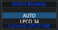
Here the user can select the runway required (or select Auto to stay in automatic mode)
Select the runway/mode desired and Long Press the encoder.
If not in Auto mode, the vILS screen will always show the airport code and runway (with red border`)

Traffic Advisory
This feature should not be used an single source for indication of other aircraft and avoidance maneuvers, the operation of this feature is very dependent on good connection to FlyData servers.
The data shown is acquired in partnership with SafeSky, not all aircraft appear since it's dependent on the aircraft have some sort of active transmitter for it's own position and data aggregators receiver network.
Optionally it's possible to have a local ADSB Receiver connected to FDR
Data sent to FDR from the server, it is limited to targets that have a maximum vertical altitude difference of +/-5000ft and a maximum distance of 14nm, maximum number of target is limited to 10 ordered by distance.
Indication of up to the three nearest aircraft
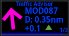
It will show:
Arrowpointing in the direction of trafficCallSignDistancein nautical millesAltituderelative altitude between traffic and FDR, altitude shown in hundreds of feet.
To cycle between the closest aircraft, perform a Short Click on the encoder to switch aircraft target.
In case of communication failure with server and no local ADSB receiver, an warning will be shown:

It is possible to pair FDR with the FDR ADSB Receiver that allows continuing visualization of targets even if server communication if down.
Radar Page
This feature should not be used an single source for indication of other aircraft and avoidance maneuvers, the operation of this feature is very dependent on good connection to FlyData servers.
The data shown is acquired in partnership with SafeSky, not all aircraft appear since it's dependent on the aircraft have some sort of active transmitter for it's own position and data aggregators receiver network.
Optionally it's possible to have a local ADSB Receiver connected to FDR
Data sent to FDR from the server, it is limited to targets that have a maximum vertical altitude difference of +/-5000ft and a maximum distance of 14nm, maximum number of target is limited to 10 ordered by distance.
Similar to the Traffic Advisory page, but instead of showing aircraft individually it shows in radar view.

The aircraft symbol is color coded:
Redrelative altitude difference bellow 500ftOrangerelative altitude difference between 500ft and 1000ftGreendefault color
It is possible to adjust the radar scale via Short Click on the encoder, the valid scales are 2nm, 4nm and 8nm.
In case of communication failure with server and no local ADSB receiver, an warning will be shown:

It is possible to pair FDR with the FDR ADSB Receiver that allows continuing visualization of targets even if server communication if down.
Alerts
CO Sensor Value
In case the CO sensor value is too high, an alert will show on the screen (And Buzzer will also beep)

The screen will blink the background color depending on the alarm level, Orange for high level, and Red for danger level.

In case of alert, the device will stay in this page while the alarm is active, the user can override this by Short Press on the encoder to exit this mode and return to normal menu.
Alert values configuration done via FlyData platform.
Messages
FDR supports receive short messages from the server (Not SMS, it requires a TCP Connection).
When a message arrives a new screen will show up:

The title, will have different background colors according to the message level set by who sent it:
BlackInfo MessageYellowWarning MessageRedDanger Message
The buzzer will also beep when a message arrive, the number of beeps and duration are related to the message level.
In case the message sent is too large to fit on the screen, the user can use the Rotary Encoder to scroll the message on screen.
The message can be sent via FlyData platform.