Display Installer - User Manual
Display to be used during FDR installation phase to check if FDR is operating normally, it allows the user check GPS State, LTE Communications state, calibration of AHRS values, etc..
It can also be used for maintenance purposes, to check device state.
The Display connects to FDR via WIFI connection.
This Display is optional to use, but advisable to validate and troubleshoot installations.
Powering the Display
The Display does not contains internal battery, it must be powered via USB-C connector connected directly to a USB receptacle on the airplane or by using a small power bank with USB Output.
The Display has a power consumption of around 1W.
Main Screen
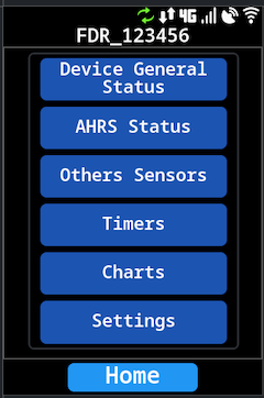
After powering the Display it is presented a main screen:
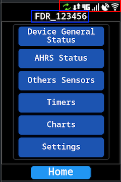
Where on TOP (Red area) there are a series of icon that indicate a quick status about connectivity from the Display and FDR connected, also an indication of which FDR we are connected (Blue Area) (Display presents the FDR Serial Number / Wifi Name).
Last FDR / Wifi network is stored in internal memory, after a Display power on the last used will be shown.
It also presents a menu to access the several Display functionality.
Symbols
List of symbols in use:
| Name | Symbol | Description |
|---|---|---|
| Wifi Status | Wifi Status, color coded - Green: Connected to WIFI Network k - Red: Not connected to a configured WIFI Network - Gray: No WIFI Network Configured | |
| GPS Status | GPS Status of FDR: - Green: GPS is FIX - Red: GPS Not FIX (or no data related to GPS) | |
| Modem Signal Strength | Indication of FDR Modem Network signal quality | |
| LTE Status | Status of FDR LTE, if the modem is registered on the network or not. connection | |
| Data communication | Indication if FDR is communicating with Server | |
| Firmware Update | Only shown in case there is a firmware update available to the Display. Requires connection to a WIFI network with internet access |
Most of symbols are more related to FDR than Display status.
Connection to an FDR Device
To connect to an FDR device, on the main screen click Settings and then Setup Wifi
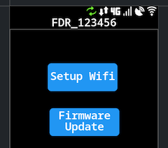
It will show a page:
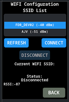
There are three main buttons:
CONNECT: Connect to the selected WIFI Network (will appear disabled if already connected to one)DISCONNECT: Disconnect from the current WIFI Network (will appear disabled if not connected to any Network)REFRESH: Refresh the list of WIFI Networks
The FDR needs to be powered, the WIFI Network created by FDR should start about 15s after power on.
Press the button REFRESH to update the WIFI Network List, this operation should take 3~4s.
After the operation concludes, select the correct FDR network from the list.
The FDR WIFI Network name (SSID) is always the FDR serial number.
Press the button CONNECT.
The Status should change to connecting and after a couple of seconds will change to Connected.
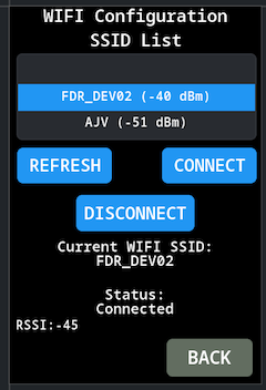
At this point should be connected to FDR press the BACK button followed by the Home to go back to main screen.
Menus
There are several menus/pages to check FDR status. When in any of these menus/pages use the Home button to go nack to the menu page
Device General Status
Quick visualization of most FDR status:
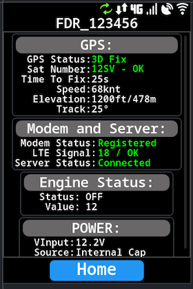
FDR main status screen.
GPS
The GPS shows some values and status of GPS, the most important ones are GPS Status and Sat Number to determine the quality of signal.
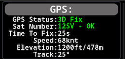
Normally (if outside) the number of satellites seen should be higher than 15 after a couple of minutes.
These values are color coded, if Green indicates that is OK, other colors indicate problems.
GPS can take up to 1min or 2min to get a valid fix after first power on (cold start), this time will depend greatly of ambient conditions.
If inside a building (Hangar) allow up to 5 minutes to get first fix after power up.
The FDR GPS Antenna must be installed in a way that it has a clear line of sight of the Sky. If FDR model with internal antenna, the FDR must be installed on the instrument panel tablier with good sky line of sight. If the FDR antenna is external, the FDR can be installed anywhere suitable but the external antenna must be placed on a location that has direct sky view with minimal obstructions, check the antenna for orientation indication.
Modem and Server
Indication of status oif LTE Modem and server connection.
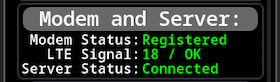
The values are color coded, being Green OK status. The LTE Signal may be OK with other colors since the value is dependent of the network signal in the location, but the other two values must be Green to be considered OK.
After PowerUp it can tale between 15s and 1m for these values become OK since the modem takes some time to register in the network, specially if it has been powered Off for a long time.
If status of the modem takes a long time to change to Registered (more than 5 minutes), check the LTE antenna, if it is connected to the correct connector.
If the situation persist, contact customer support to check if the SIM Card is activated.
If using FDR with external cable antenna, place the antenna is somewhere it has a visibility to outside the airplane, put it away from metallic objects and try to keep it at least 10~15cm away from other transmitting antennas.
Engine Status
Indication of the status of the engine status detection, it also shows the current value used for the that detection.

This value is an average of the accelerometer noise being detected by the device. Depending on installation location and airplane airframe construction the default settings may need to be tune to the specific aircraft.
With the engine off, it is expected this value to be lower than 15 (it can be influenced by people moving inside the cockpit), and with engine on the expected value is higher than 45.
User should attempt to turn ON and OFF the engine to see if the detection is OK.
Device may take up to 15~20s to detect an engine ON and engine OFF, this is to avoid false positives in case of movement inside the cockpit influencing the values.
If the engine detection does not work (too low value for engine ON or too high value for engine OFF), annotate the values that where seen for booth situation and pass them to customer support, in order to reconfigure the FDR unit with correct values for that installation.
Future firmware version of Display will have the ability to configure these values on FDR.
Power Status
Indication of the voltage value FDR is being supplied and it's source.

In normal circumstances this value should the airplane battery value.
AHRS Status
visualization and calibration of AHRS
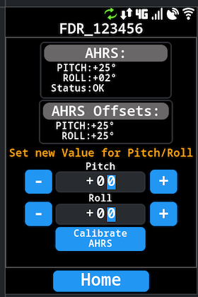
AHRS
Current values the device is reading from AHRS.

After installation the values of Pitch and Roll may be wrong, depending on the FDR installation orientation and specially the Pitch the airplane may have when on Ground. It may be necessary to calibrate the AHRS values by indicating the offset for each value.
The Status will indicate if the values are valid or not, it will be in Initializing until the GPS Fix is OK and there are more than 7 satellites and the GPS Module indicates that the fix quality is acceptable.
If powering FDR inside a building allow some time for the GPS module to get a good quality fix, depending on the building structure this may not be possible, it is advisable to have the airplane outside.
AHRS Offset
Current AHRS Offset values configured on the FDR device.

AHRS Calibration
Allows the user to program new Pitch and Roll values on FDR, FDR will take this values as an offset to compensate the readings. This is valid to compensate values up to +/-15º if the readings from FDR with the Offset at 0 is higher than that, contact customer support for advice.
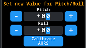
To calibrate new values, just input the correct Pitch and Roll values, and press the button Calibrate AHRS
The fact that on Ground the AHRS are not zero, is not incorrect since it depends on the airplane attitude on Ground. To more accurately calibrate AHRS check the values that other airplane instruments are reading on that condition to match booth.
Other Sensors
Values for other FDR internal sensors.
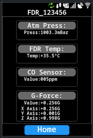
This values are shown just for reference.
As a guide:
Atm Pressnormal value between 995mBar and 1020mBar (depends on atmospheric conditions)FDR Temparound 25~35ºC if FDR is under the instrument panel, up to +85ºC ifFDRis in directly sun light exposure.CO SensorAfter installation value should be lower than 5 (ideally 0), if value too high it may represent some problem in the airplaneG-ForceDepends onFDRmounting, but typicallyXandYnear 0 andZaround 1.
Timers
Values for FDR internal timers
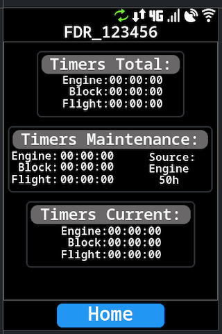
These are the values for FDR timers, related to Engine Time, Block Time and Flight Time. There are three main group of timers:
CurrentCurrent cycle time recorded since last event (Engine ON,Block Start,Flight Take-Off)- All three values start at
0as long aEngine Onevent is detected. - If device has
Engine Offwill show the time counted for last event
- All three values start at
MaintenanceCumulative time recorded since last maintenance- Indication of Maintenance time source as well number of hours between maintenance
- Time values will have different colors depending if over maintenance time of very close (less than 2h)
TotalCumulative time recorded since the device was installed or the timer was last reset.
Currently the Maintenance timer is only possible to be reset/configure via FlyData platform. In future firmware version this Display it will have that ability.
Charts
Visualize some FDR sensor data in charts.
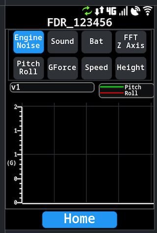
With the exception of FFT Z Axis that is a real time value, all other values present an history of 60s, new value every second.
Firmware Update
This section is related to update the firmware of the Display, not the FDR firmware. The FDR firmware is handled directly by the communications server.
In order for the firmware update of the Display to work, it needs to be connected to a WIFI network that has internet access.
The FDR generated WIFI network is not suitable to this, since it does not allow internet access
Access the Firmware menu, in Settings / Firmware Update
After being connected to an Wifi network with internet connection, the status should be Waiting to start....
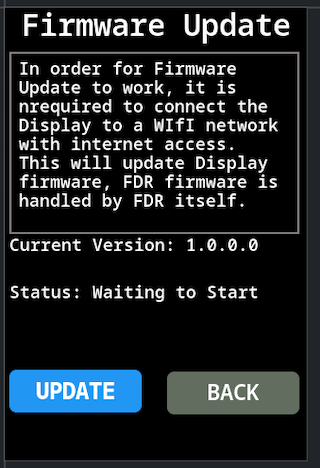
Press the button Update the status information should change to Starting Firmware Update, if the indication No Update Available shows it means that no new version is available on the update server.
The indication Starting Firmware Update may last for quite a while (30s), before changing status to Downloading. This will be redesigned in future versions to improve user experience.
If a firmware version is available the display will download the new version, the status will change to Status: Downloading firmware… with an indication of the progress percentage.
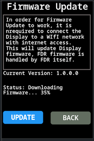
Upon downloading the new firmware version the Display will reboot to apply the new firmware.